Sooo…. Computer doesn’t boot. You’ve tried swapping memory, you’ve tried booting with no battery, you’ve tried the usual disconnect-all-non-essential-components, and whatever. The computer powers on, but either goes into a cycle of turn on – wait a few seconds – turn off or the screen just stays blank.
Chances are, you are dealing with a corrupted BIOS (Basic Input Output System) firmware. This is the little bit of software that goes on a computer that controls how the hardware operates – and gives an interface for software to run on it. If you want an explanation of what BIOS is, see this video: https://www.youtube.com/watch?v=zIYkol851dU
This firmware can break in a couple of different ways. The most common way is when it tries to automatically update, generally pushed through Windows Update along with other more minor software updates. The trouble is, if for any reason a firmware update gets interrupted, it cannot roll back and clean up – it bricks the computer. The other common way is if you have an HP computer – in which case it just randomly kills itself. I’m not sure why, but HP computers often experience random firmware self-destruction.
Here’s how to recover it.
First: Try automatic recovery methods
Most computers already have built-in recovery methods in case this happens. I’m going to gloss over them because most are already well documented, but these are the main 3 options available:
Full Resets
This is the easiest thing to try, and always the best first step. Sometimes, what looks like an issue from corrupted firmware is just a lockup of some sort, or a pending update that got stuck before it started. Full reset means to disconnect ALL power sources from the computer – power cable, battery (for laptops), and the internal CMOS battery – and hold the power button pressed for 10-15 seconds to drain all power from volatile chips in the computer. You can remove the RAM memory cards as well, for good measure. Then reconnect everything and power the computer back on.
USB Key BIOS Recovery
If the computer’s firmware is actually corrupted and not self-recoverable, many models have the capability to recover firmware from a USB drive, even if the computer will not boot. The procedure for this varies by computer manufacturer, so look up documentation for your specific model for instructions. In general, the procedure is to make a USB drive containing the firmware files (by downloading a firmware update from the manufacturer’s website and extracting it to the drive), plugging the drive into the dead computer and powering it on holding a specific combination of keys (this combination varies by model – for some HP laptops, for example, it’s Fn + B).
Dual BIOS Systems
Some computers (mostly desktops) have a backup BIOS chip – with a procedure to make the computer boot from it instead of the main, broken one. Again, this procedure varies by manufacturer, so look at the documentation for your specific computer to figure out how.
If all else fails, the nuclear option
Step 1: Stuff you’ll need
Step 1.1: Find a new BIOS
The first thing you will need, is, of course, a good copy of your computer’s firmware, in a binary file format that you can write back to the BIOS chip. Depending on the computer model you’re working with, there may be a backup copy of the BIOS firmware saved on the hard disk, you may be able to use a download from the manufacturer’s website, or you could find a “BIOS dump” from the Internet from someone else who has the same model laptop as you and uploaded a copy to a forum site.
For HP laptops, whenever the computer does a BIOS update, it saves a copy of the old BIOS to a partition on the hard drive. This will be a small (2GB or less) partition called “Recovery” or “HP Tools”. Take out the hard disk (or SSD) from the non-working computer, plug it into another computer, mount the partition and open it. Within it, find a folder called Hewlett-Packard, and within that a folder called BIOS, and within that 3 subfolders: Current, New and Old. Find a BIN file (named along the lines of 083C8.BIN or some 5 character hexadecimal name), in the Current or Old folders. This is your recovery copy.
For other makes and models, you might be able to get a copy of the BIOS from the manufacturer’s website. Go to the support downloads page for your laptop, find a BIOS update (equal version or newer than what is on your computer), and download it. Extract it – either using 7-zip or by running the given executable and having it extract contents to a folder or USB drive. Go to the folder it extracted to, and search for a .BIN or .ROM file of a round size, like 8MB (8192KB), 16MB (16384KB), or 32MB (32768KB). Some computers, especially desktop motherboards, will have odd extensions (often just 3 random alphanumeric characters). The tie together is that they are all binary format files. However, if you find a file that is of a size that is not a direct power of 2 like above, like HP computers with an 8.4MB BIN file, this is a compressed capsule file that cannot be used. You could possibly extract this using tools (look at InnoExtractor or similar), but it gets difficult.
When the above two fail, and you do not have any intact copy of your computer’s firmware, you can search the Internet for a copy. Sometimes, people who have made a copy of their computer’s firmware for any other reason will upload it for people to use. You can do a search for your computer model followed by “bios dump” to find it. Some good sources include badcaps.net forums and vinafix.com forums (the latter one is a paid site). If that turns up nothing, you can search for your computer’s motherboard model instead of the computer model itself (this will usually be printed on the motherboard itself, and look something along the lines of LA-9781P (a Dell Precision M6800) or so).
Step 1.2: Another working computer
More specifically, a working computer running either Linux (you can use any Windows laptop and make a Linux live bootable Linux USB drive – Ubuntu or Linux Mint works best) or Mac OS. The issue with Windows is that the software for USB EEPROM readers does not work well (compatibility issues with the device drivers).
Once you have the recovery machine booted to Linux (or a Mac), install the programming software, ‘flashrom’. The easiest way to do this is from the command line.
On Linux, run two commands (connect to the Internet first, of course):
1) sudo apt-get update
2) sudo apt-get install flashrom
On Mac OS, first install Homebrew (https://brew.sh/), then the Terminal command:
brew install flashrom
Step 1.3: A USB EEPROM chip reader
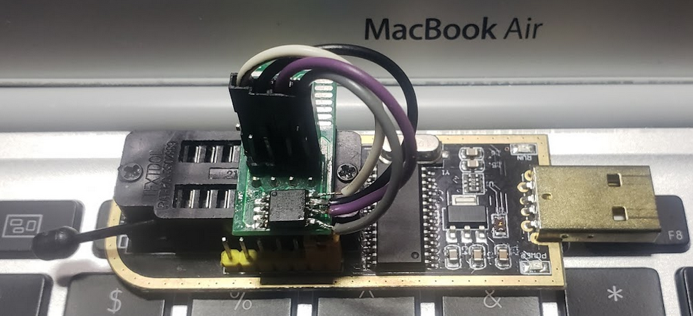
Since the target computer cannot start at all, we need external access to the firmware chip to replace its messed up contents with an intact, working firmware. To do this, you need what is called a USB EEPROM programmer. This tool has an interface to the chip (an SPI interface) with a connector or header for a connector to the (generally 8 pin) BIOS chip on one side and a USB on the other. Like this:
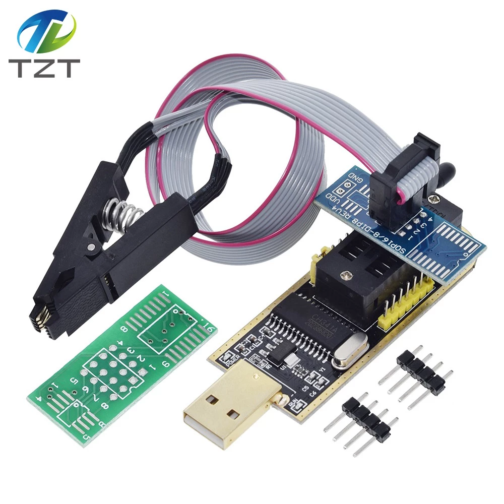
By far the most common model of EEPROM programmer is the CH341A (pictured above). In addition to the programmer itself, you need the chip interface itself. For many chips, an SOIC 8 clip (the thing on a cable pictured above) will work. For others, like socketed desktop motherboard chips or anything that you have to desolder, a clamp like this would be more convenient:
These can be had for $10-15 on eBay (or possibly cheaper). Note, do not pay more for higher quality SOIC clips – they are all weak.
Step 2: Find the BIOS chip on the mainboard
Time to take the computer apart. If it’s a laptop, take off the bottom cover (or if your laptop is designed such, the keyboard and palmrest panel – search the internet for teardown guides for your model laptop). If it’s a desktop, remove the side panel and take out whatever components you need to get a clear view of the motherboard. You’re looking for a chip like one of these:
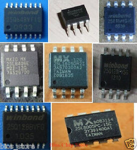
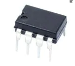
Most BIOS chips are 8 legged, more or less square, and look like that. Note that many other power circuitry components may look similar – to find which one is a firmware chip, look for something marked with brand names like Winbond, MX, Atmel, or similar and with part numbers starting with 25Q, 25L, 25W or 25X (like 25Q32, 25Q64, 25Q128, 25W80, or such).
Some chips are different shape – like:
– 16 pin SOIC spider chip (note that if this is your case, an SOIC8 clip won’t work and you will need an SOIC 16 clip (wider) instead)
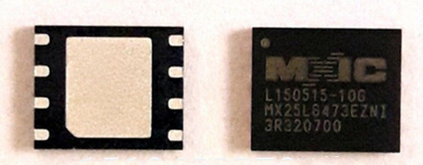
– Flat, surface-mount-device (SMD) chip – for example on Apple MacBook Pro laptops (look like this):
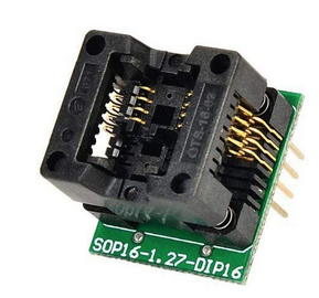
– Socketed chips – mostly found on home-builder focused desktop computer brands (Asus, MSI, Gigabyte and the like). These look like this:
On desktop motherboards, they are generally in the lower right corner of the front face of the circuit board. On laptops, it can be just about anywhere, but generally physically close to the CPU socket. It could be on either face (top or bottom) of the mainboard, and you may very well have to remove the board from the computer to find it.
If you can’t find it, get a lamp and a magnifying glass and look again 🙂
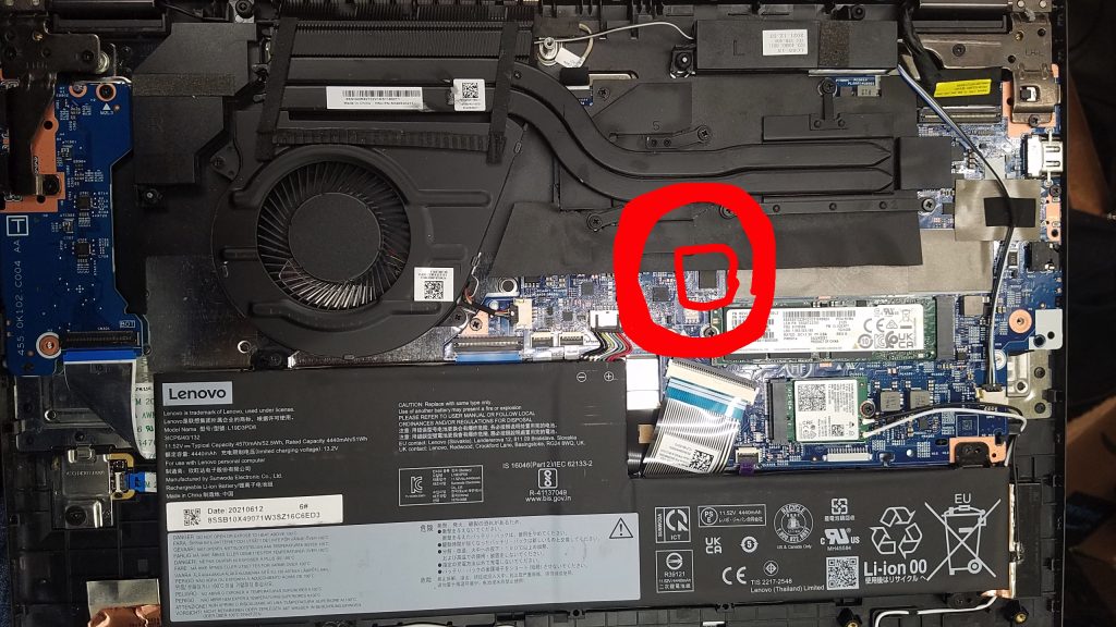
For example, on a Lenovo IdeaPad Flex 5, this is where the chip was:
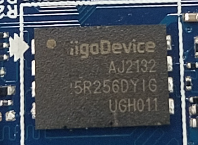
Side note, this Lenovo IdeaPad (a Flex 5 15ITL05) had a BIOS chip from an unusual brand – GigaDevice, and a 256Mbit (32MB) surface mount chip:
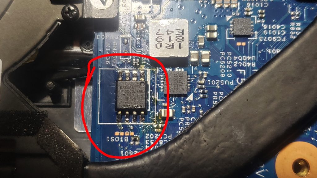
Meanwhile another laptop, an HP Pavilion X360 15-bs121nr has it near the CPU fan on the back edge:
Other examples include the Lenovo ThinkPad T440P (which has it on the bottom near the RAM slot) and W540 (top face of the motherboard, on the right side), HP EliteBook 8740W and 8560W (near the RAM slot on the bottom) and Dell Precision M6800 (bottom face of motherboard, by the CPU heatsink mounting plate)
Note: Many computers have two identical BIOS chips, right next to each other. In these cases, one of them contains the Intel Management Engine firmware. It’s often the larger of the two chips – for example, the Management Engine firmware will be on an 8MB (64 mega bit, 25Q64 model) chip, and the system BIOS on a 4MB (32 mega bit, 25Q32 model) chip.
The Management Engine firmware sometimes gets corrupted, too, often resulting in a boot loop. If this gets corrupted, the re-flashing procedure is identical to the main BIOS chip, except you need a dump of normal contents of that chip. You have to find this on the internet – automatic BIOS backups do not contain it.
Step 3: Attach your programmer tool to the BIOS chip
Socketed Chips (Mostly on Desktops)
These are easy. You pull them out of the socket (usually you can do so with just your fingers), and then use a chip socket (as shown in step 1). Place the chip (upside down, usually, or according to the manual for your programmer tool if it had one) so that pin 1 (indicated on the chip by a dot or a dip in one corner) lines up with a pin 1 indicator on the socket.
8 Pin SOIC Spider Chips
For this type of chip, the SOIC clip is the easiest way to go. Simply squeeze the clip, and clip it on to the chip. Make sure that the clip stays on, and that each of the clip’s 8 terminals, which are all on the inner surface of the clip, are each firmly making contact with the corresponding pin on the chip. Each terminal needs to touch the side of the chip’s legs, not the top tip. You may need to hold the SOIC clip with a downward force pushing it onto the chip with your hand or a strap for it to maintain contact.
Make sure to line up the pins correctly. Pin 1 of the chip is generally marked by a dip or a white dot in a corner of the chip. Pin 1 on an SOIC clip is usually marked by a red stripe on one of the wires – so make sure to attach the clip so that the terminal with the red stripe wire lines up with the pin of the chip at the dot or dip corner.
8 Pin SOIC Spider Chips, Again – That You Have to Solder
Sometimes, just putting a clip does not work. In some cases, it simply does not make good contact. In other cases, the computer’s circuitry has a write protect applied to the chip – this is done by electrically pulling down one of the chip’s pins (most chips have such a pin) – Apple iMac for example does this. In yet others (like my HP EliteBook 8740W), the laptop’s circuitry drains power away from the chip (I think) when you try to connect to it while still on the board. In these cases, you have to physically de-solder the chip from the computer circuit board and attach it to the programmer.
This gets… tricky, and you run a very high chance of severely damaging the computer circuit board while doing this – if one of the small electrical traces on the circuit board that connects to the chip is over heated or pulled too hard, it will break off the board, destroying the computer’s connection to the chip, killing it forever and resulting in a tedious and rather microscopic surgery being needed to add a bypass wire to work in place of the broken one. BEWARE!!!
Before you start removing the chip, make a mark on the circuit board indicating the orientation the chip went in.
My method of desoldering these 8 legged chips is to apply solder flux paste to the terminals, use a wide soldering tip to heat a row of 4 pins at a time, and then lift each row off the board individually.
By wide tip, I mean this, that can make contact with and heat all 4 pins of one side of an SOIC chip at a time:
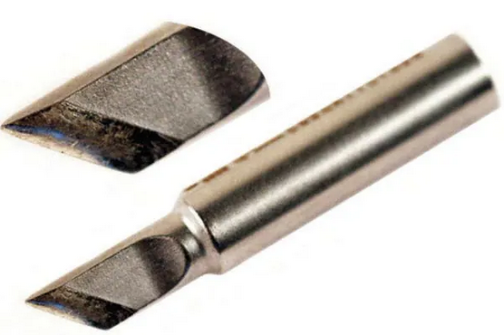
When you use it, make sure the tip is clean and not covered in oxide, because any oxide on the tip reduces its ability to transfer heat to the job. Rub the tip with a fine file or sandpaper, then melt a bit of solder wire metal on the tip and wipe it off.
Heat the soldering iron up (if your solder machine has temperature control, I used 375 degrees), and press the wide tip so that it touches all the pins on one edge at a time, and hold it for a few seconds until the solder at the joints melts. Then, once it melts, still holding the hot tip to the terminals, insert a very thin flat tip screwdriver underneath the tip and twist it (very gently!!!) so as to raise the melted side of the chip off the board, by about one millimeter. Do not apply force to remove it, or you will break terminals! The solder joints need to be fully melted, at which point it will lift off easily.
Now heat the pins on the other edge of the chip, in the same manner. Wait for the solder joints to fully melt, and this time instead of using a screwdriver to pry the chip up, push the chip sideways with the soldering iron tip to move it off the melted solder pads. The chip should now be loose from the circuit board.
With the chip out, you have a couple of ways to attach it to the programmer. The easiest is to use the chip socket, as I mentioned earlier for socketed chips. If you don’t have a socket, most programmers come with a little circuit board meant for soldering chips to. I often connect chips like this, by soldering thin wires to the chip, because my programmer’s solder board terminals don’t line up with most chips:
Again, make sure you line up the pin numbers.
Surface-mount / flat chips
For these, the only way to do it is to desolder the chip and connect it to the programmer tool. These are fairly easy to desolder – but you need a hot air soldering machine, not a hot tip soldering iron. Use a 1/4″ or so nozzle tip on the hot air gun, set the temperature to about 375 degrees (or higher as necessary – Apple laptop boards need about 415) and hold it about half an inch above the chip until the solder melts. Once it does, use a tweezer to pick the chip off.
Once it’s removed, the best way to connect it to the programmer tool is to solder 8 small wires to the tiny terminals on the bottom of the chip and plug it into the pins on the programmer tool.
Step 4: Flash the new BIOS
Step 4.1: Install flashrom
Once you have the recovery machine booted to Linux (or a Mac), install the programming software, ‘flashrom’. The easiest way to do this is from the command line.
On Linux, run two commands (connect to the Internet first, of course)1) sudo apt-get update
2) sudo apt-get install flashrom
On Mac OS, first install Homebrew (https://brew.sh/), then the Terminal command:
brew install flashrom
Plug in the EEPROM programmer with the chip attached to it, and test to make sure the computer can read it properly. Run this command:
sudo flashrom -p [whateveryourprogrammermodelis]
replace [whateveryourprogrammermodelis] with the model of your EEPROM programmer tool. For example, for a CH341a programmer, use sudo flashrom -p ch341a_spi .
It should detect a chip model, then stop saying No operations specified. It may also ask you to manually enter the BIOS chip model. However, if it says No EEPROM Chip Found, it means you need to double check the connection between the chip and the programmer. Make sure the SOIC clip is firmly attached or your soldered jumper wires are making good contact.
If you get an error saying “Programmer initialization failed”, make sure the chip is not connected backwards. In my experience, this error comes when the chip is connected reverse.
Step 4.2: Make a copy of the old BIOS
Doesn’t matter if your old BIOS doesn’t work anyways – Murphy’s Law states that anything that can go wrong, will go wrong. So, make a copy of your old BIOS, just in case the new flash goes worse.
To read the contents of the chip to a file, the command is (assuming ch341a_spi for the programmer model):
sudo flashrom -p ch341a_spi -r old_backup.bin
this saves the old BIOS to a file called old_backup.bin in your user’s home folder.
It’s best to make at least two copies of the old one and make sure that they match, to ensure that the programmer is working properly. Run the above command again, with a new filename, then use the command
diff backup1.bin backup2.bin
to compare them. The command should run with no output, indicating that they match. If it says the files differ, then you need to solidify the chip-to-programmer connections.
Step 4.3: Flash the new BIOS
Put the new BIOS file in the user’s home folder, then run:
sudo flashrom -p ch341a_spi -w new_bios.bin
(You need to make sure the file you are trying to flash to the chip is of exactly the same size as the chip itself, or flashrom will complain. If it’s not, you probably have the wrong BIOS backup / fresh file.
Wait for it to finish, detach the chip from the programmer, and if you detached the chip from the motherboard, attach it back, re-assemble the laptop, pray to whatever god(s) you believe in, and press the power button. If all went well, it should boot. Note that it will almost certainly take an unusually long time to show anything on the screen – it needs to validate the new BIOS.
Some computers, like HP ones, will complain about serial numbers if you flash a fresh BIOS with no serial number programmed into it. (On my Pavilion X360 15-bs121nr, it disabled TPM altogether because of missing serial number). You can use tools like HP BIOS Config Utility to fix this (on HP machines). Note, do NOT waste time with the HP DMI Tool, it does not work. On anything.