Problem Description
No display backlight – the laptop would power on as normal, you could hear the startup chime, but the screen stayed blank. I could see an image on the screen, though – by shining a flashlight at the screen. Just no light coming from the screen – the actual LCD layer and graphics processor worked, but the light part didn’t.
Computer details
Apple MacBook Pro 16,4 – 2019 16″ Intel Core i9 + Radeon GPU model, macOS Catalina 10.15.7 (though issue is OS independent). (Mainboard model #: 820-01700-A)
What was wrong
The LCD backlight power supply circuit on the laptop’s mainboard was shorted due to a failed capacitor -bridging the supposedly 50 volt line supplying the display directly through ground through it.
The circuit supplying power to the display backlight has several capacitors connected between the supply line and the computer’s ground/negative line, used to “smooth out” fluctuations in the voltage being supplied. Normally, these capacitors act as buffers when the voltage supplied is suddenly slightly higher or lower, and don’t let any current flow through them to ground. However, when one of them fails, like had happened here, they turn into conductors – letting power flow straight through them from the supply line to negative/ground. Electricity flows through the path of least resistance – in this case, through the shorted capacitor instead of through the actual backlight. So, obviously, the screen stays dark.
The problem doesn’t have anything to do with the graphics processor or GMUX chip. This was also not the result of liquid damage – there were no signs of liquid spill at all, anywhere in or on the laptop.
How to fix
First, make sure the issue is what you think it is – check that the laptop is properly on (fans spinning?) and that you can actually see an image (no matter how faint) on the screen when a light is shined on it. If you can’t see anything, you probably have a different issue. If you can, proceed.
First step to try of course is to make sure the display connector itself is clean (not rusted or anything). The connector is in the middle of the rear edge of the computer – a snap connector that is under two metal strips with screws to hold it on. This thing:
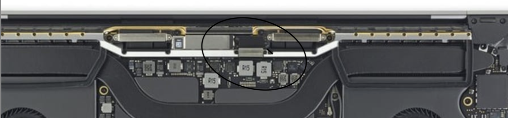
Take off the covers, unsnap it, and clean both parts of the connector with isopropyl alcohol.
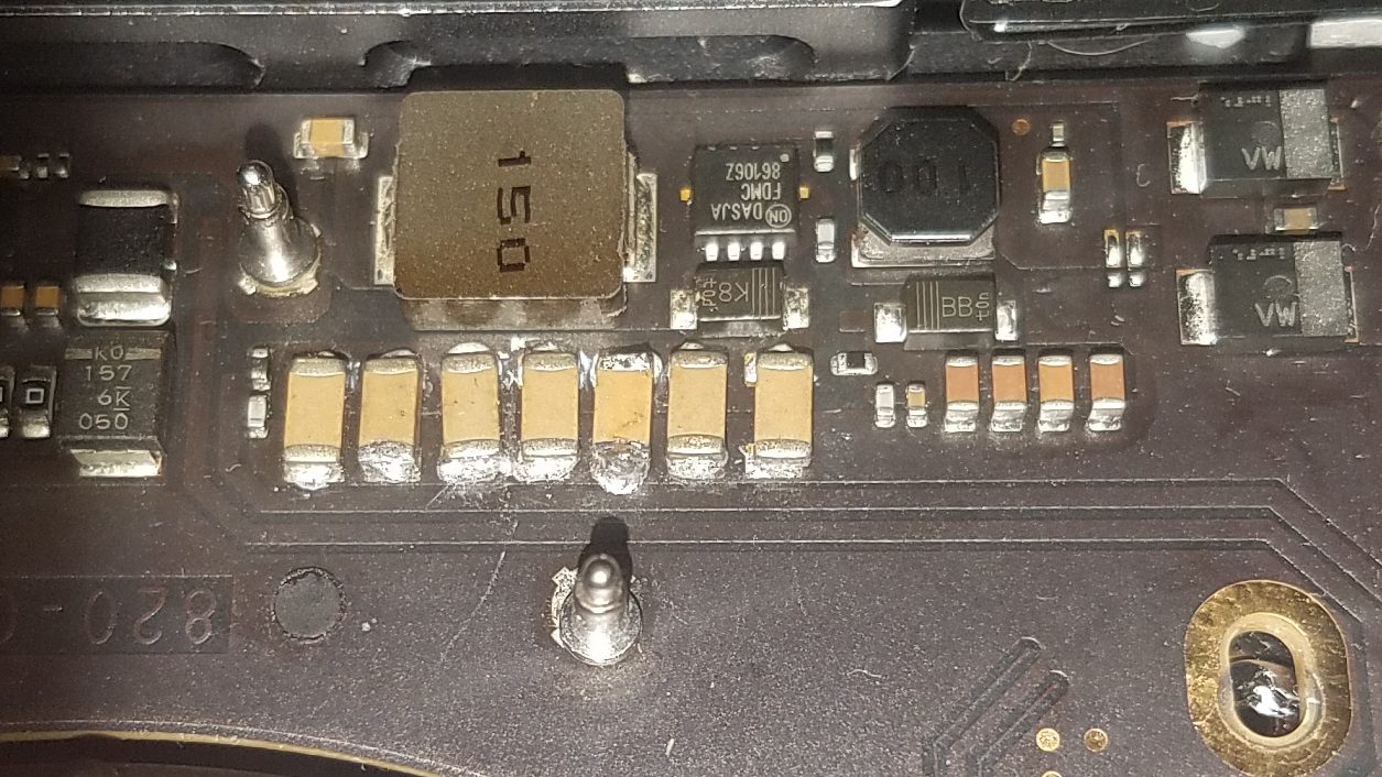
Still nothing? Time for circuit troubleshooting. With the laptop on, get a multimeter, touch the negative probe to one of the screw holes on the mainboard, and the positive tip to one or more of the lower (battery-side) terminals of these brown capacitors in the row:

Those points are all part of the “PPVOUT_S0_LCDBKLT_F” power line – and should have a voltage of about 50 volts (or 45-50, maybe some more but about that much). If you have voltage here, (shut down the laptop of course), take the mainboard out of the computer and check the inboard end of the display connector mentioned earlier for any poor connection signs.
If you get 0 or close to 0 volts at those points, like was the case with mine, shut down the laptop, remove the battery (you have to remove the ribbon cable that goes over the battery terminals and then unscrew the screw that holds the battery flap terminal down), and then put the multimeter in resistance/continuity mode and check between the same points from earlier to ground (a screw hole will do for ground). This should be an open circuit – or if not, should have a very high resistance (900-1600 ohms). On the machine I was working on, though, it was only 55 ohms – far too low. This is what’s called a “short to ground” – the result of some component that has connections to both the power line and ground failing internally and bridging the two when it’s not supposed to.
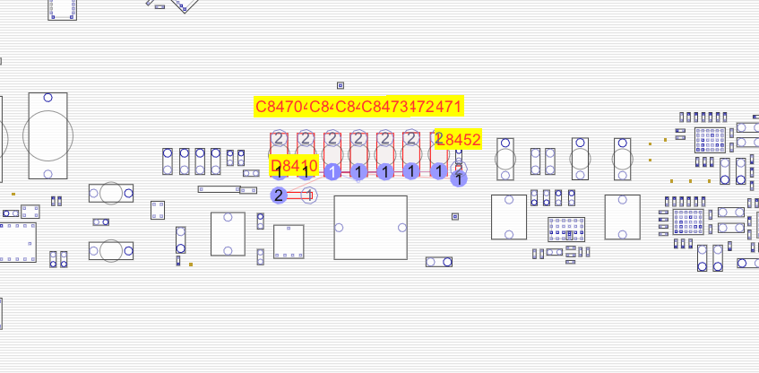
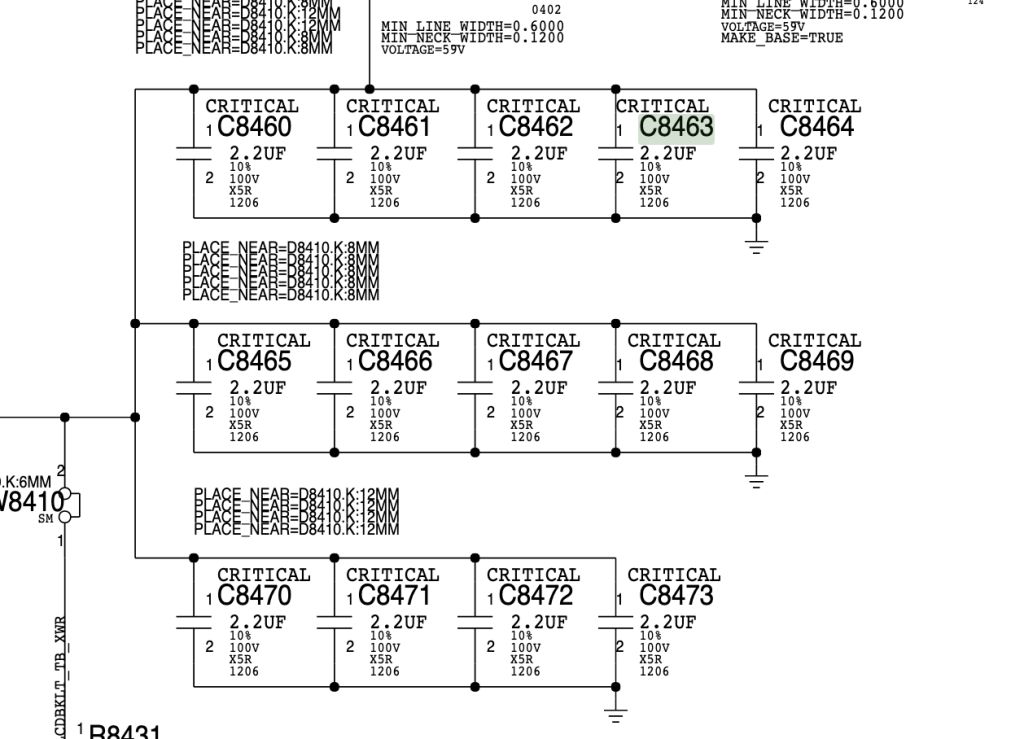
This can be caused by any number of things, but the most likely cuplrit is the numerous capacitors present between the PPVOUT….LCDBKLT line and ground. There’s 14 of them total, seven shown above and another seven on the other face of the circuit board, in the same location. They’re numbered C8460 through C8473 in the schematics.
Check for any visible damage (discoloration, charring/burnt spots, or blown components). If there isn’t any, it can be quite hard to tell which component is shorted. There’s a way to find it by feeding a low voltage (like 1 v) from a bench power supply through the circuit and either using a thermal camera or spraying isopropyl alcohol on the area and watching where it evaporates soonest to see which component is shorted, since the shorted component will warm/heat up as the excess current flows through it. I couldn’t figure out how to do this, though, so feeling rather confident that the problem was one of the capacitors, went for a shotgun approach – keep removing capacitors until the short goes away. Crude approach, but worked.
Now for the difficult part – soldering. Ideally, you would use a pair of “hot tweezers” to just desolder and pick off the SMD components in one go. Something like this:
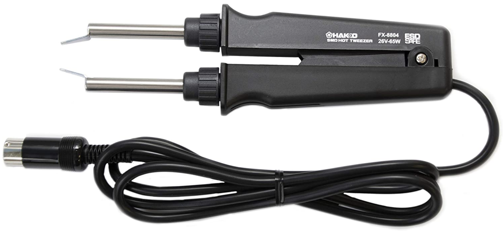
If you have one of those, or can buy one, great! You’ll save yourself quite a lot of headache. But if you don’t, you can do this with a hot air soldering machine. (A regular soldering iron won’t work since both sides of the component need to be heated simultaneously).
Hot air desoldering stuff from an Apple circuit board isn’t easy. They use a solder metal with a high melting point, and the board design soaks up heat too easily. What worked for me was to use a 1/2″ (or so) diameter nozzle on my hot air gun, set the temperature to 400 degrees C, use a gooseneck clamp to hold the tip about 1/2″ off the board, and heat it for a good 1-2 minutes. (I’m sure experienced electronics technicians will want to bite me for some or all of that crude work and torture of a circuit board- but this was my first time and it was being stubborn, okay?!). Keep trying to pick the component off with a sharp tip tweezer – don’t apply force though, when it is melted it will come off very easily. In this manner, heat and pick off the brown capacitors. I found it best to remove the whole row at once, because they’re all together and being heated anyways and it’s better to not keep repeatedly heating the thing up.
Be very, very careful not to knock off any nearby tiny components while the thing is softened/melted!!! Some of the components are extremely tiny and will come off by accident easily. In my case, a tiny capacitor (CC785 in the schematic) came off like this, and try as I may I could not solder the little (1mm in its longest dimension) component back on. (Luckily, it was one of 4 capacitors connected in parallel and the computer seems to work properly even without it).
In my case, the shorted capacitor was in the row of 7 on the bottom face of the mainboard (the face that touches the keyboard). So it might be a good idea to remove that row first. (A failure could happen anywhere, though, so YMMV).
After you’ve removed one row of capacitors (or however many you removed in one go), check the resistance between the two terminals where any one of those capacitors was. If you see the same low resistance as earlier, keep removing capacitors. If not, check the resistance each of the capacitors you removed and identify which was shorted.
The brown capacitors are 2.2 microfarads, 100V. As you can see in the schematic:
Once you have the replacement capacitor(s) (I salvaged these from a dead A1990 MacBook Pro (2018 15″ model), time to solder it back. This is by far the most difficult part of the whole job. Again, there’s probably a much better and/or easier way to do this, but here’s how I did it:
Step 1) Apply fresh solder to the pads where the capacitors are to be soldered, with a regular soldering iron. Note that, counterintuitively, tiny soldering iron tips do NOT work for power line connections like this! They don’t transfer enough heat for the beefy (relatively) solder points to melt. You need a reasonably big tip. Melt some fresh solder onto it and touch to the pads/solder points for the capacitors.
Step 2) Heat the area up again, same procedure as earlier. Once the solder is melted (try poking it with a tweezer / tiny screwdriver tip to check), pick up the SMD capacitors with the tweezer, and very carefully, place them into position. Nudge it sideways if necessary with the tool tip so that they’re perfectly lined up, then press it down so it’s flat against the mainboard.
Step 3) Once that’s done for all the capacitors, take off the hot air, and inspect the solder joints. In my case at least, some didn’t look right, and I had to re-melt them with an iron tip. Again, tiny tips do NOT work, you need a reasonably fat one. A chisel tip worked well for me.
Check for nearby components that may have gotten knocked over or dislodged. If there are, hold them down with a tweezer tip, and use the iron to melt each end of the component one at a time to re-form the connection.
My final job came out looking like this:
Yeah, not great (looks okay here but from other angles, nah). But it did work, and I spent so long trying to get it done that I wasn’t willing to mess with it any longer. experienced technicians, please don’t eat me, it was my first time 🙂
Also that little spring loaded stand thingy at the bottom of the photo came off with the heat, and I had to re attach it.
Finally! Do a final resistance check to make sure the short is gone, re-assemble the Mac, plug in the power, pray to whatever god(s) you believe in, and press the power button. If all is well, you’ll see a fully lit image on the screen. And maybe get the daylights scared out of you when it delays starting the fans for a few seconds making you think the machine might be dead and then it suddenly screams the startup chime at full volume through the 16″ MacBook Pro’s renownedly-loud speakers right as you’re tensely watching it without even making the sound of your breath :p Totally, definitely not speaking from experience.
All done, good night!

Schematics for this model (invaluable for any circuit troubleshooting):
https://www.badcaps.net/forum/showthread.php?t=87287
Also thanks a million to user 2informaticos from the Rossmann Group forums: